Modern vehicles have evolved into complex ecosystems of electronics, sensors, and data networks. As cars become increasingly intelligent and interconnected, one of the most persistent challenges for auto technicians is diagnosing intermittent electrical faults and CAN-bus communication errors. These issues are elusive, irregular, and capable of mimicking other failures—making them one of the most time-consuming repair categories in the industry.
Understanding the Complexity of Intermittent Electrical Faults
Unlike consistent malfunctions, intermittent faults appear sporadically—only under certain conditions like vibration, heat, humidity, or voltage fluctuation. This unpredictability makes them hard to reproduce in workshop conditions. In modern vehicles equipped with 50+ ECUs and high-speed communication systems, these issues can cascade across modules, producing unrelated fault codes and misleading symptoms.
Key reasons these faults are difficult to isolate:
-
Temporal behavior – The problem might vanish before the technician starts diagnosis, leaving no active fault codes.
-
Interlinked systems – A fault in one circuit (e.g., a corroded ground) can trigger errors in unrelated modules via CAN-bus data corruption.
-
ECU sleep/wake cycles – In newer vehicles, certain ECUs deactivate when inactive, masking the fault until the correct wake condition occurs.
-
Environmental triggers – Condensation, road salt, or thermal expansion can cause contact failures that appear only after hours of driving.
To tackle these, technicians need both data-driven tools and advanced analytical reasoning—going far beyond a simple OBD scan.
Step 1: Precise Fault Capture and Contextual Data Collection
Capturing when and how the fault happens is crucial. The first step isn’t touching the car—it’s gathering contextual intelligence.
Techniques include:
-
Detailed customer interviews to identify exact conditions of occurrence (e.g., “only when headlights and AC are on simultaneously”).
-
Freeze frame data extraction from diagnostic tools to analyze voltage, speed, temperature, and load when the fault was triggered.
-
Using dataloggers that record real-time CAN signals over several hours or days while the vehicle is driven in typical conditions.
-
Video correlation by mounting a dash camera synchronized with data capture to visualize when the fault appears.
By documenting these details, technicians can pinpoint environmental or operational factors that align with the fault event.
Step 2: Deep Analysis of CAN-Bus Communication
The CAN-bus network is the central nervous system of modern vehicles. When data frames become corrupted or delayed, modules may drop communication, triggering random warning lights or limp-home modes.
Advanced diagnostic approaches include:
-
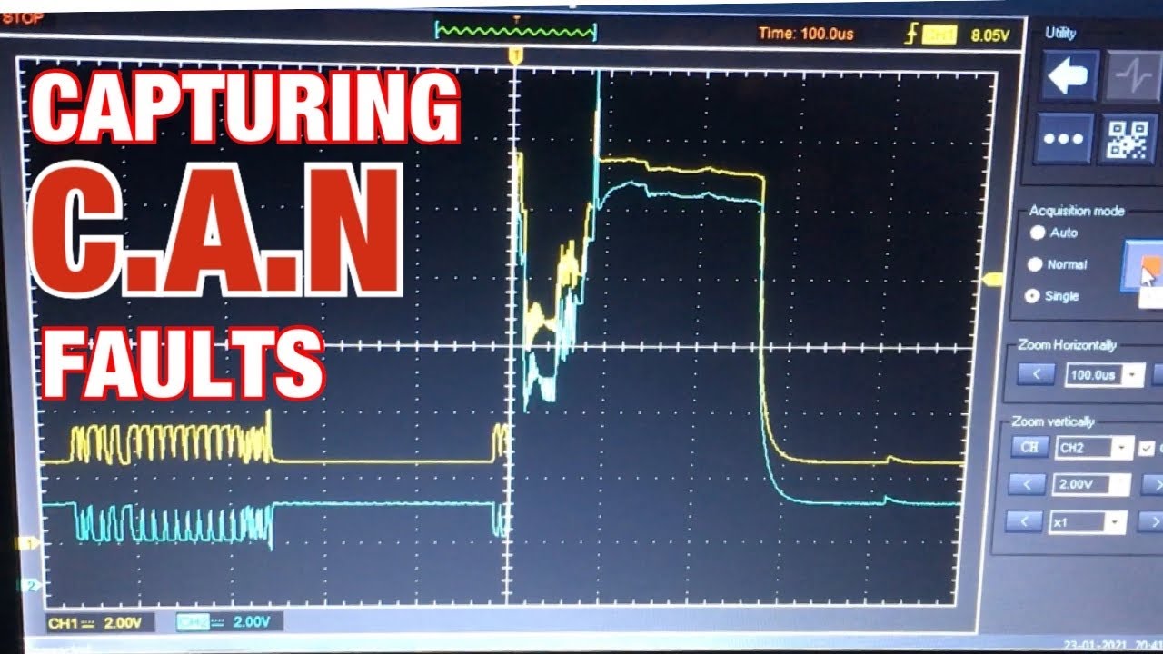
Oscilloscope waveform analysis – Observing physical signal integrity (voltage levels, reflections, noise). Deviations from the 2.5 V reference on either CAN-H or CAN-L indicate wiring or termination issues.
-
Bus load testing – Determining if the communication bandwidth is saturated by malfunctioning nodes or external interference.
-
Termination resistance verification – Measuring 60 Ω between CAN-H and CAN-L ensures both 120 Ω terminators are healthy and connected.
-
Error frame counting – Specialized CAN analyzers can record how often nodes transmit error frames, pinpointing the misbehaving ECU.
Technicians should also examine gateway modules since many modern vehicles feature multiple CAN segments bridged together (Powertrain, Body, Infotainment). A single compromised line can propagate faults across entire systems.
Step 3: Environmental Stress Testing
Once initial analysis narrows down potential suspects, stress testing helps reproduce the fault on demand. This step validates whether temperature, vibration, or movement is influencing the circuit.
Effective techniques:
-
Thermal testing – Use of heat guns or freeze spray on suspect areas such as connectors or wiring looms to see if the fault reappears.
-
Harness manipulation – Carefully moving wiring while monitoring voltage and CAN signals to detect intermittent opens or shorts.
-
Humidity simulation – Moisture can bridge terminals in weather-exposed modules, so controlled exposure can confirm corrosion issues.
-
Voltage sag testing – Simulating low battery or alternator load conditions to verify system resilience under stress.
By controlling environmental conditions, you can trigger the fault in the workshop instead of relying on unpredictable road tests.
Step 4: Advanced Electrical Measurement Techniques
Beyond basic multimeter testing, modern diagnosis requires high-resolution data capture and dynamic signal analysis.
Tools and methods that elevate precision:
-
Graphing multimeters to track live voltage drop across circuits during real operation.
-
Oscilloscopes with math functions for evaluating differential CAN voltages and detecting cross-talk.
-
Low-amp current probes for parasitic drain tracing in intermittent battery discharge cases.
-
Thermal imaging cameras to locate hidden resistance points, overheating connectors, or poor grounds.
-
Load-testing circuits instead of continuity checks—ensuring wires hold current under operational stress.
Each method focuses on capturing transient electrical behavior that static readings overlook.
Step 5: Software-Level Diagnostics and Firmware Integrity
Modern ECUs rely on firmware and configuration data that can themselves become corrupted. An intermittent fault isn’t always hardware—it could be software inconsistency.
Recommended procedures:
-
Check for corrupted parameter files or mismatched software versions across networked modules.
-
Perform checksum verification using OEM diagnostic tools to ensure firmware integrity.
-
Re-flash ECUs only after confirming voltage stability and clean communication, as improper reprogramming can worsen CAN issues.
-
Monitor network topology after software updates, since new calibrations may alter message IDs or gateway routing.
A disciplined approach to ECU software validation prevents repeat repairs and misdiagnoses related to logical faults.
Step 6: Proactive Preventive Measures and Repair Validation
Once the fault is resolved, confirming long-term reliability is essential. Modern repair validation involves both post-fix testing and predictive monitoring.
Recommended steps:
-
Extended test drives with CAN data logging to confirm network stability.
-
Implementing vibration and moisture protection (dielectric grease, heat-shrink, loom shielding).
-
Updating workshop knowledge about known manufacturer service bulletins related to intermittent faults.
-
Conducting predictive diagnostics using machine learning-enabled scanners that compare live vehicle data against known healthy profiles.
By validating the repair in multiple conditions, workshops can confidently prevent recurring issues.
The Future of Fault Diagnostics: AI-Assisted Predictive Maintenance
Artificial intelligence is reshaping automotive diagnostics. Predictive systems now learn from large datasets of CAN traffic, enabling early detection of anomalies before drivers notice symptoms. AI algorithms monitor communication latency, frame error rates, and voltage variance patterns—flagging modules that deviate from the norm.
In electric and hybrid vehicles, where high-voltage management systems rely heavily on flawless data exchange, predictive diagnostics will become vital for both safety and uptime optimization.
Technicians who adopt AI-driven diagnostic tools will gain a competitive edge, as they can identify potential network degradations weeks before they manifest as breakdowns.
FAQs
1. Why do intermittent electrical faults rarely show up in diagnostic scans?
Because fault codes only register when a malfunction persists long enough for the ECU to log it. Intermittent issues often resolve before detection.
2. How can oscilloscope analysis improve diagnostic accuracy?
Oscilloscopes display real-time voltage behavior, revealing signal distortions or dropouts invisible to standard multimeters or scan tools.
3. Are CAN-bus errors always caused by wiring faults?
Not always. They can result from failing ECUs, software corruption, poor terminations, or voltage instability across modules.
4. What’s the role of network gateways in diagnosing communication errors?
Gateways bridge different CAN segments. A fault in one side of the gateway can disrupt data flow across multiple systems simultaneously.
5. How can workshops prevent repeat CAN-bus failures?
By reinforcing connections, updating software regularly, validating repairs under real driving conditions, and documenting all diagnostic findings.
6. Is AI-based predictive maintenance reliable for real-world workshops?
Yes, when used as a supplementary tool. It enhances human diagnostics by identifying subtle electrical anomalies through pattern recognition.
7. Can environmental factors permanently damage CAN networks?
If unchecked, yes. Moisture, heat, and vibration can corrode terminals or damage insulation, leading to irreversible wiring harness issues.
